1. February 2022 By Andreas Liesche and Anna-Franziska Eckert
Variant configuration (part 4) – engineers, programmers and IT as agile teams
The second blog post saw us taking a virtual bike tour from sales to production and optimising the order acquisition and order fulfilment processes. We saw how individual products can be developed and manufactured with profit margins in mind, leveraging the help of a configurator, a development kit and automation. To do so smoothly, it is indispensable to use modular variant models, continuous processes and the integration of the respective leading IT systems.
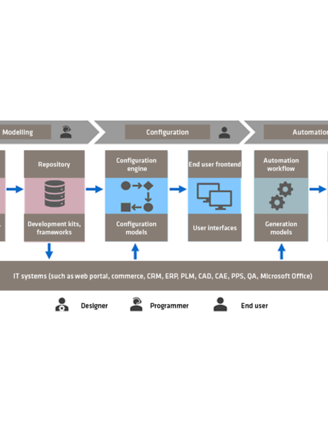
We want to now take a look at the architecture and components of an integrated variant configuration system that are necessary for successful realisation. The following figure shows an example of the individual modules for modelling, configuration and automation and their interaction.

Modelling methodology
The modelling of product configurators is primarily associated with the definition of classes, characteristics, characteristic values and dependencies (high-level configuration). In this way, it is easy and convenient to model configurators with low to medium complexity for sales support. A typical configuration result is a complete and valid characteristic value assignment as a basis for possible subsequent processes such as pricing and quotation generation.
It makes sense at the beginning of the modelling to describe the required variance and the permissible solution space. Variant structures, elements, properties, options and dependencies must be taken into account. It is very useful to use a tree-like structure to depict this. This tree is mapped by parent–child relationships, starting from the root node. Element properties are defined as characteristics and can take on different characteristic values. Domains are defined as lists of values or ranges of values. In so doing, the maximum solution space is completely defined.
The addition of object dependencies narrows the solution space. Variance in the structure consists of options and alternatives, that is, a generic element can be omitted or present and realised by different objects. Variance in the characteristic value assignment also consists of options and alternatives, meaning that a feature can be omitted or present and require the assignment of a valid value. The configuration is complete and valid when all necessary characteristics have been assigned permitted values and all necessary elements have been assigned matching parts.
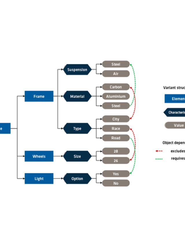
The structure of a variant structure with elements, characteristics and values and the associated dependencies are explained using a simple configurable bicycle with a few components as an example.

The bicycle consists of the frame, wheels and light. Structural elements are specified by characteristics. These characteristics can take on characteristic values. The element ‘frame’ is defined by the three characteristics type, material and suspension. The characteristic ‘Type’ can take the values City, Race or Road. The ‘Light’ element is optional and can be deselected. Further elements, characteristics and characteristic values are modelled in a similar manner.
Now you can define dependencies. The example shows two types of rules: ‘excludes’ and ‘requires’. A ‘Race’ bike does not come with 26-inch wheels and a ‘Road’ bike needs lights. The bicycle configuration model is now complete. The system must ensure that all rules are followed when configuring a bicycle variant.
In practice, it must also be possible to model very large configuration models. It makes sense then to break down the variant structure so it can be built up modularly. Nowadays, there is a large development kit of tried-and-tested tools and functions available for mapping object dependencies. A modern variant configuration system should be able to support the maximum number possible of different powerful modelling methods and rules. Many different methods, objects, data and frameworks are used in combination to map complex product, system and solution configurators.
A variant development kit is based on an object library with ATO (assemble-to-order), CTO (configure-to-order) and ETO (engineer-to-order). These objects and their relationships can also map multi-level modular variant structures (low-level configuration). In addition to the characteristic value assignment, a product structure variant is now also created as a configuration result as the basis for further subsequent processes such as the generation of parts lists, work plans, spare parts lists and visualisation.
Complex configuration projects must be modularised. Typical modules include: product catalogue, guided selling, requirements specification, product comparison, configuration and automation of subsequent processes. It is easier, from an IT perspective, to integrate these modules on the basis of a consistent higher-level configuration system than to have to implement complex interfaces between many systems.
State-of-the-art configuration models of any complexity level can be modelled, tested and rolled out. These can consist of all basic data, high-level and low-level frameworks, derivations of user-specific user interfaces and integration of external systems based on a modular configuration framework using a integrated development environment (IDE).
Modelling environment
The integrated modelling environment provides a variety of convenient functions: project definition and structure, class and object system, data entry and editing, import and export, modelling of the framework, flow control and user interfaces. In addition, there are management and integration processes that can be automated for versioning, test management and model generation, including delivery to the runtime environment. Many other functions are available as IDE plugins.
The configurator modelling can be done with different working methods:
- Model-oriented methods: This method is well-suited for engineers, for example. Modelling can take place in the form of mind maps, tables, arithmetic and logical expressions. Model-oriented tools are easy and quick to learn. Programming knowledge is not required to get started. However, there are limits to the complexity that can be mapped.
- Code-based methods: This method is suitable for people with IT and software knowledge. Modelling is typically done in a domain-specific language (DSL) or by means of scripting. Code-based tools have a steeper learning curve. Basic knowledge of programming is helpful. However, the analytical approach makes it possible to map any number of complex models.
Challenges that typically arise with both approaches include:
- Any coordination between departments and implementation is difficult
- Data creation and rule modelling are usually very time-consuming
- Maintaining data and the rules increases the workload on a regular basis
- Graphical modelling quickly reaches its limits when dealing with complex issues
- The quality is endangered by coding or scripting without knowledge of programming
These typical challenges can be mastered well today. A modern state-of-the-art modelling environment supports different work methods on a uniform data model. This makes it possible for experts from different disciplines to work together on the configuration projects with the help of customised methods and tools. Collaboration in cross-disciplinary teams enables efficient and effective modelling and maintenance and operation of configuration models with any level of complexity.
With a modern modelling environment, configuration projects with predefined folder structures are created very easily and the desired model files are generated, edited and validated on the basis of templates. Configuration models are versioned and managed as modular projects. Various editors with different user interfaces are used to edit the model data. In this manner, experts in the engineering department and software developers in the development department can work very well together in a team using tools they are familiar with and according to their expertise.
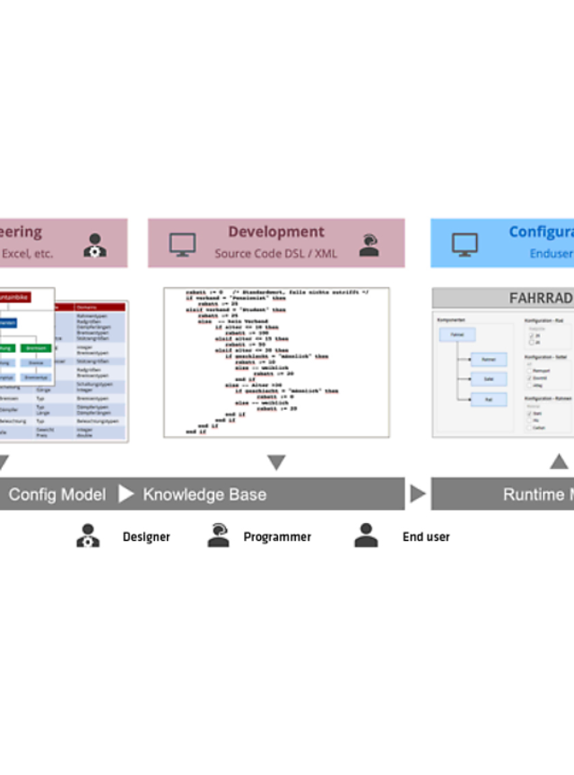
The following is a schematic diagram of the data model.

It is possible for experts in the engineering department to implement the technical modelling preferably by means of mind maps, tables and rule editors. Software developers in the development department can continue to use code-based development as before. An integrated modelling environment with different editors and tools enables flexible and agile collaboration between experts, developers and programmers.
An approved package of the model data in the configuration project is the knowledge base for the derivation of an executable knowledge base (KB). This contains all relevant data, rules and external references for generating data-driven user interfaces. This results in many advantages and great flexibility in the frontend design. A standard interface for testing the configurator can be generated fully automatically. Optional UI customising enables customised user interfaces for different end user roles.
Interactive configuration
The KB is exported after modelling, testing and approval of the configuration model. The user starts the configuration, and then the runtime environment initialises the appropriate knowledge base, generates the dynamic product structure, executes the high-level and low-level object dependencies, updates the model and generates the dynamic user interface. Every interaction by the user triggers a round trip: The model is re-evaluated and the frontend is updated.
A distinction is made between two different operating concepts:
- Secured configuration: This operating concept is a good basis especially for users without training. It starts with a valid initial configuration. The framework is used to avoid conflicts. Its operation is simple and secure, but the configuration can run into a dead end. This means that desired options may not be available later on due to preselected options and dependencies. Now users have to go back one or more configuration steps and correct their selection before the configuration can be continued.
- Open configuration: This operating concept for trained users and professionals can start with an empty, incomplete, valid or invalid configuration. This allows for a distinct interactive application. The framework is used to detect and display possible error conditions. Functions for guided or automatic conflict resolution or targeted optimisation can support the user in the process. This operating concept is clearly more demanding; however, all degrees of complexity can still be mapped.
There are key success factors of both operating concepts: The user interface must be adapted to the respective end users (customer, partner, sales, project planning, design, planning, production, service) in the best possible way and be intuitive to use.
The configuration in terms of sales is often supported by dynamic pricing and delivery scheduling. Furthermore, dynamic 2D or 3D viewing models are very interesting. Users can view an individual representation of their current configuration at any time. These additional attractive sales and marketing functions can significantly support the customer’s final purchase decision.
The configuration result is available at the conclusion of this process. It can be saved for the next time or placed in the shopping basket for enquiries or orders, or even forwarded. Automated subsequent processes can be triggered on this basis, for example, including pricing and quotation generation for the customer or the generation of data and documents for internal order processing, as well as commissioning and service.
A variant configuration system is not an isolated solution
Integration into the existing system landscape is an extremely important factor. The configuration system needs to access information in the connected IT systems and store generated results there. The partially or fully automated generation of all necessary data and documents for order processing processes offers considerable potential for digitalisation and, in turn, the potential to save time and reduce costs. We need to eliminate media disruptions and redundant manual data entry.
What happens next?
We have looked at the typical architecture of an integrated variant configuration system and the sub-areas of modelling and configuration in particular in this blog post. In the next post, we will focus on the automation of the subsequent processes. The big bang approaches that were used traditionally have rarely been successful. This is an extremely complex task. We will show how step-by-step agile implementation can be achieved through the use of innovative automation workflow technologies. It is worth leveraging the considerable ratio potential of digital order processing. If you’d like to learn more about this topic, then please get in touch with us – we’d love to hear from you.
Are you interested in which areas we at adesso provide our manufacturing industry customers with support? Then check out our website.


